ESP32 motion detector switch with PIR and relay
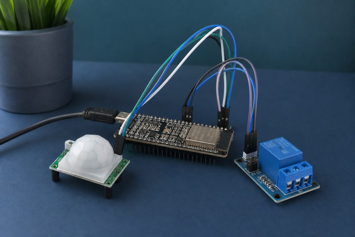
Wire an HC-SR501 PIR and a 5 V relay to an ESP32, then run a hold-timer sketch so a lamp or fan turns on when someone walks by. Diagram, pin map, and full program included.
This build is a motion switch: the PIR sees a person, the ESP32 holds a timer, and the relay closes so a lamp, fan, or 12 V LED strip turns on. The MCU never switches the load itself. GPIO18 only drives the relay IN pin.
Works on classic ESP32 and ESP32-S3 DevKits. GPIO4 and GPIO18 are not boot-strap pins, so an active-low relay will not click or trap the chip in download mode at reset.
What you need
1. ESP32 DevKit (classic or S3) and a USB-C cable.
2. PIR HC-SR501 (5 V, three pins: VCC, OUT, GND). AM312 is a 3.3 V alternative; then VCC goes to 3V3, not 5V.
3. 5 V relay module with opto and IN / VCC / GND. Confirm if IN is active LOW (most blue boards) or HIGH.
4. Jumper wires and a USB 5 V supply that can feed the relay coil.
5. Load on COM/NO only: 12 V LED strip, or a mains lamp in a closed fused box.
Do not put 220 V on a breadboard.
Pin connections
ESP32 5V -> PIR VCC and Relay VCC
ESP32 GND -> PIR GND and Relay GND
ESP32 GPIO4 -> PIR OUT (input, motion = HIGH on HC-SR501)
ESP32 GPIO18 -> Relay IN (output; LOW = on if the module is active-low)
Relay COM -> load supply (lamp live, or 12 V +)
Relay NO -> switched side of the load
Common ground is required. Leave NC unused. If your PIR is AM312 (3.3 V), move VCC to ESP32 3V3 and keep GND and OUT the same.
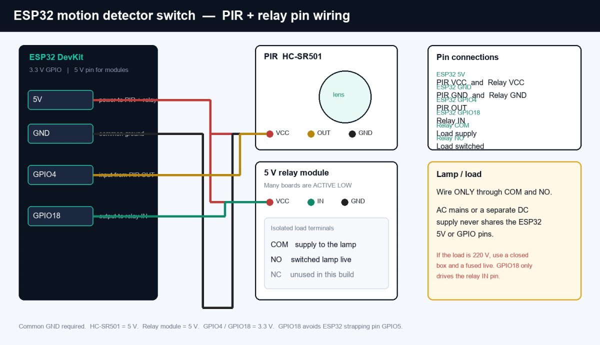
How to wire it
1. USB-power the ESP32. Confirm 5V and GND with a meter.
2. PIR VCC to 5V, GND to GND, OUT to GPIO4. Set the HC-SR501 time pot near minimum; the sketch owns the hold time. Sensitivity pot mid.
3. Relay VCC to 5V, GND to GND, IN to GPIO18. JD-VCC jumper stays on if the board has one and you are using one 5 V rail.
4. Load: break the live (or the 12 V +) through COM and NO. Neutral / 12 V - goes straight to the load. Fuse the live if it is mains.
5. Point the PIR away from the relay and away from HVAC. Heat and sun false-trigger it.
HC-SR501 needs about 30 seconds after 5V is applied before OUT is trustworthy. The program waits for that.
Program
Arduino IDE: board = ESP32 Dev Module (or ESP32S3 Dev Module). Port = the USB COM. Upload, open Serial at 115200, wait for Ready, then walk in front of the lens.
If the relay is on when nobody is there, your module is active HIGH: set RELAY_ACTIVE_LOW to 0. If OUT stays HIGH, check 5V on the PIR and the warmup delay.
// ESP32 motion detector switch
// PIR HC-SR501 on GPIO4, 5V relay module on GPIO18
// Arduino-ESP32 (Arduino IDE or PlatformIO)

#define PIR_PIN 4
#define RELAY_PIN 18
#define RELAY_ACTIVE_LOW 1   // 1 = most cheap modules; 0 if IN is active HIGH
#define HOLD_MS 15000        // keep the load on this long after last motion
#define PIR_WARMUP_MS 30000  // HC-SR501 needs ~30 s after power-up

bool loadOn = false;
unsigned long lastMotionMs = 0;

void setRelay(bool on) {
  if (RELAY_ACTIVE_LOW) {
    digitalWrite(RELAY_PIN, on ? LOW : HIGH);
  } else {
    digitalWrite(RELAY_PIN, on ? HIGH : LOW);
  }
  loadOn = on;
}

void setup() {
  Serial.begin(115200);
  pinMode(PIR_PIN, INPUT);
  pinMode(RELAY_PIN, OUTPUT);
  setRelay(false);
  Serial.println("PIR warmup...");
  delay(PIR_WARMUP_MS);
  Serial.println("Ready. Walk in front of the lens.");
}

void loop() {
  int motion = digitalRead(PIR_PIN);
  unsigned long now = millis();

  if (motion == HIGH) {
    lastMotionMs = now;
    if (!loadOn) {
      setRelay(true);
      Serial.println("Motion: relay ON");
    }
  }

  if (loadOn && (now - lastMotionMs >= HOLD_MS)) {
    setRelay(false);
    Serial.println("Timeout: relay OFF");
  }

  delay(50);
}
What you should see
Serial: Motion: relay ON, then Timeout: relay OFF after 15 s with no new HIGH on GPIO4. The relay LED follows IN. The load follows COM-NO.
Change HOLD_MS for a longer lamp. Add a second GPIO later for a manual override or for MQTT. For an S3 pin map of the rest of the header, see the ESP32-S3 pin post.