GY-291 ADXL345 Accelerometer Module – Triple Axis Digital Gravity Sensor (3-Axis) for Arduino, Robotics, and Motion Detection Projects
GY-291 ADXL345 Accelerometer Module – Triple Axis Digital Gravity Sensor (3-Axis) for Arduino, Robotics, and Motion Detection Projects
The GY-291 ADXL345 Accelerometer Module is a high-resolution, low-power 3-axis digital acceleration sensor designed for accurate measurement of motion, tilt, and vibration in embedded systems. Built around the ADXL345 chip from Analog Devices, this module is capable of sensing acceleration in the X, Y, and Z axes with up to 13-bit resolution, making it ideal for a wide range of motion-sensing applications.
The ADXL345 supports both I2C and SPI digital communication interfaces, offering flexibility for integration with Arduino, Raspberry Pi, ESP32, STM32, and other microcontrollers. It can measure both static acceleration (gravity) and dynamic acceleration (motion or shock), with a selectable measurement range of ±2g, ±4g, ±8g, or ±16g.
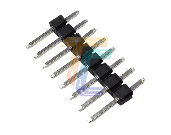
The GY-291 breakout board is compact, lightweight, and features clearly labeled pin headers for easy prototyping and PCB mounting. It’s commonly used in robotics, smartphones, step counters, drone stabilization, and gesture-based control systems.
Key Features:
Sensor Chip: ADXL345
Axes: 3-axis acceleration (X, Y, Z)
Measurement Range: ±2g, ±4g, ±8g, ±16g (selectable)
Resolution: Up to 13-bit
Output Interface: I2C or SPI (selectable)
Supply Voltage: 3V to 5V (compatible with 3.3V and 5V systems)
Low Power Consumption: Ideal for battery-powered devices
Built-in Tap, Double Tap, Free-Fall, Activity/Inactivity Detection
Mounting Holes and Standard 2.54mm pin spacing for breadboards and PCBs
PCB: Compact, durable module design with onboard voltage regulator
Customize PCB
Customize PCB
 Need help building your PCB Message us on Facebook!
📩 INQUIRE with us on Messenger
PCB Layout & Design Services
We provide professional PCB layout and design services for electronics projects, prototypes, and small to medium production needs. Our goal is to deliver accurate, manufacturable, and well-documented PCB designs tailored to your specific requirements.
How to Request a PCB Layout/Design:
- Send your complete schematic or diagram via our Facebook page.
- We will assess your diagram and provide a quotation based on the complexity and requirements.
Special Offer for New Customers!!
New customers receive a special introductory discount on their first PCB layout/design project.
This allows us to review your design requirements and build a long-term working relationship.
How to Request a PCB Layout / Design
- Send your complete schematic or diagram via our Facebook page.
- Our team will review your diagram carefully to understand the design scope and requirements.
- A detailed quotation will be provided based on:
-
- Design complexity
- Board size and number of layers
- Components and package types
- Special routing or manufacturing requirements
📌 Providing your diagram is essential so we can give you an accurate and fair quotation.
PCB Layout & Design Requirements
To ensure quality and accuracy, please note the following:
- All schematics must be clear, complete, and properly labeled
- Specify:
- Board dimensions (if available)
- Number of PCB layers
- Preferred components or footprints (if any)
- Hand-drawn, unclear, or incomplete schematics are not accepted
- Rush or urgent requests may incur additional charges
What’s Included in the Design Package
Each completed project includes the following deliverables:
✅ 2D PCB layout images
✅ 3D PCB render images
✅ PCB Gerber files (ready for fabrication)
✅ Bill of Materials (BOM)
✅ Component Placement List (CPL / Pick-and-Place file)
✅ Wiring diagram (PDF)
✅ PCB board layout (PDF)
All files are prepared to be manufacturer-ready and easy to review.
Pricing Information
Pricing is project-based and depends on:
- The submitted schematic or diagram
- Board size and layer count
- Types of components used (SMD, through-hole, fine-pitch, BGA, etc.)
- Design complexity and routing difficulty
📌 Final pricing is confirmed only after reviewing the client’s diagram.
Design Review & Approval Process
Before final delivery:
- The client will receive preview files for checking
- Please review carefully for:
- Errors
- Missing information
- Clarifications or revisions
- Once the design is confirmed and approved, the final files will be sent to the client’s email
⚠️ After final approval, any major changes may be treated as a new request.
Payment Methods
Philippines (Local Clients):
- GCash
- Bank Transfer
International Clients:
- PayPal
📌 Design work starts after payment confirmation unless otherwise agreed.
SHOP Now and Enjoy Discount

![]()
Learn With CraftedTech Engineering
Learn With CraftedTech Engineering

Welcome to Learn With CraftedTech Engineering – your go-to hub for mastering the fundamentals and innovations in engineering and technology. Whether you're a student, hobbyist, or professional, our tutorials, project guides, and hands-on resources are crafted to empower your learning journey.
From Arduino and automation systems to PCB design, 3D models, and real-world engineering applications, we break down complex topics into easy-to-understand lessons. Explore, build, and innovate with us — because at CraftedTech Engineering, we don’t just teach; we craft your future innovations.
Share


